How to edit
Best Practices:
- Always begin by modifying the lower layers (e.g., intermediate data) before moving on to higher layers (e.g., master data).
- When making any edits, set retain_edit = 1 to ensure changes are saved; if retain_edit = 0, modifications will be lost in the next run. This rule does not apply to changes made in comments.
- When creating a new entry, ensure that the ID is always unique.
- Always use lowercase.
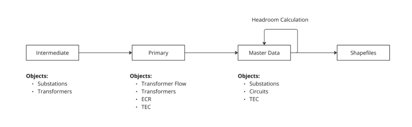
Simplified Data Workflow
Substations
Adding a new substation
- Create a new substation entry in the intermediate substation table
- Ensure that the fields in green are populated:
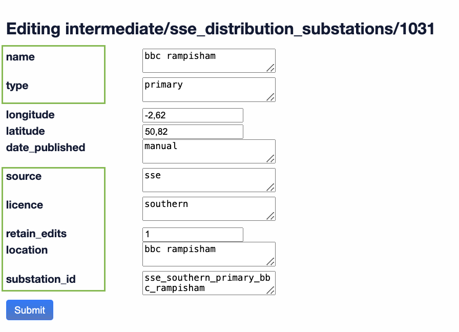
- Each substation_id must be unique and adhere to the following format:
source_[licence]_type_location
- Create a new transformer entry in the intermediate transformer table
- Ensure that the fields in green are populated:
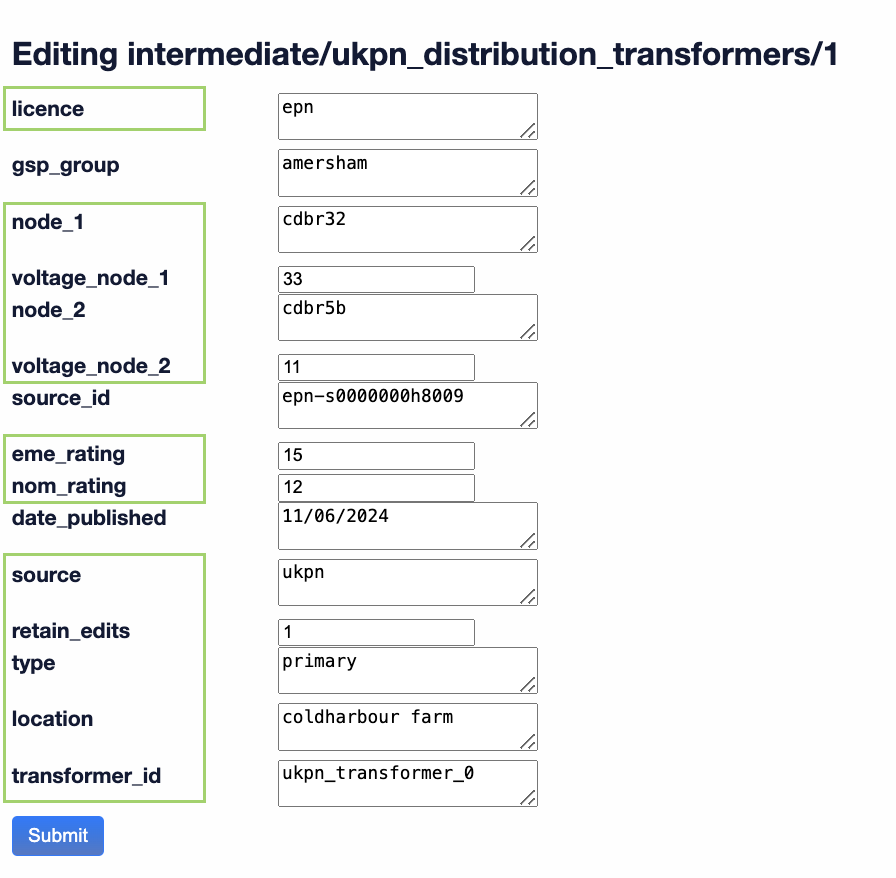
- Each transformer_id must be unique and adhere to the following format:
source_transformer_number
- For SSE, SPEN, and UKPN, transformer node 1 and node 2 are used to assign a substation to a circuit node.If a circuit node matches a transformer node, the circuit node will be assigned to the corresponding substation associated with that transformer.
In the primary transformer table, transformers are grouped by voltage and substation id.
- To reassign a transformer to a different group, modify the transformer_id (in green) with the relevant ID.
- To reassign a transformer group to a different substation, modify the substation_id (in red).
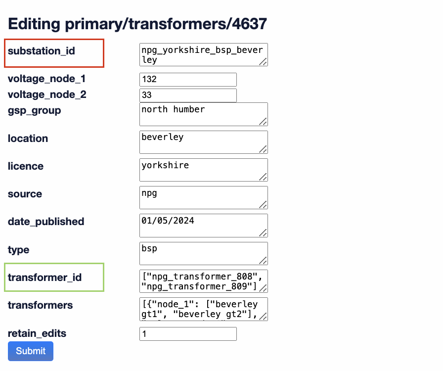
The modification of the primary transformer table should only be done as a last resort, if updating the intermediate transformer or substation table does not resolve the issue.
- Create a new transformer flow entry in the primary transformer flow table
- Ensure that the fields in green are populated:
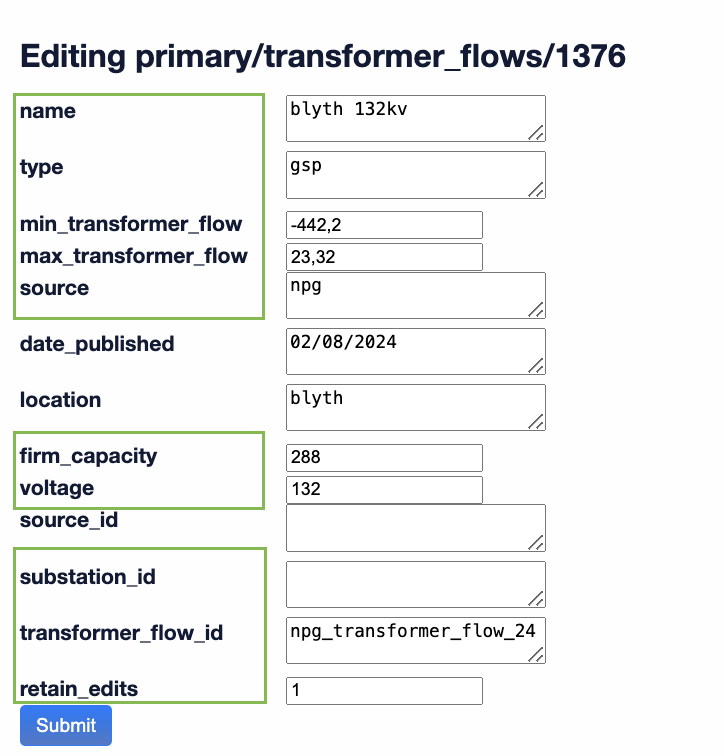
- Voltage coherence is required for NPG, ENW, SPEN, and SSE. For ENW, the voltage must correspond to the input voltage of the targeted transformer of the substation. For NPG, SPEN, and SSE, it should reflect the output voltage of the transformer. For other providers, the voltage can be set to 0.
- Each transformer_flow_id must be unique and adhere to the following format:
source_transformer_flow_number
Project
Adding a new ECR project:
- Create a new project entry in the primary ecr table
- Ensure that the fields in green are populated:
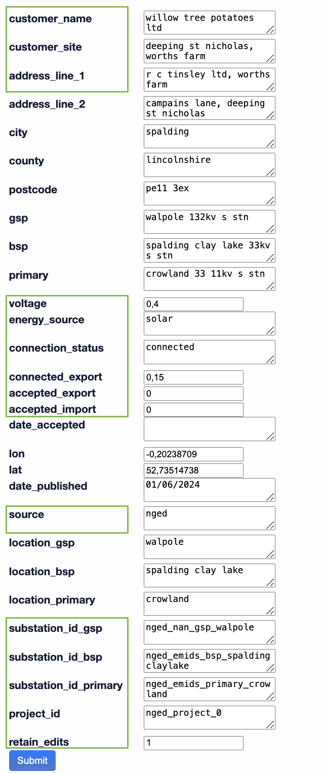
- At least one of the following must be defined when assigning the project ECR to a circuit node: customer_name, customer_site, or address line 1.
- Project voltage should represent the output voltage of the transformer to be considered in the headroom calculation of the substation.
- Each project_id must be unique and adhere to the following format:
source_project_number
Circuits
Adding a new circuit:
- Create a new entry in the master data circuits
- Ensure that the fields in green are populated:
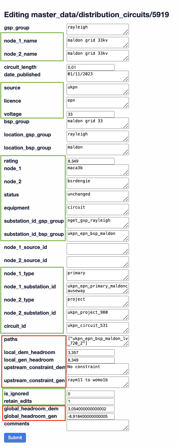
- Node 1, Node 2, Substation_id_gsp_group and Substation_id_bsp_group are used in headroom calculations to determine the appropriate paths, so they must be consistent with the other circuits.
- The fields highlighted in red are the ones updated with the headroom calculation.
- Each circuit_id must be unique and adhere to the following format:
source_circuit_number
How are master_data_substation fields computed?
Substation_id
| Object |
|
|
Object Fields Used |
|
| Substation |
Source |
Licence |
Type |
Location |
| Transformer |
Source |
Licence |
Type |
Location* |
| Transformer Flow |
Source |
Licence |
Type |
Location* |
| ECR |
Source |
Type |
Location* |
|
*Fuzzy matched (a method for identifying strings that are similar but not identical, making it useful for matching data with typos, misspellings, or minor differences)
| Provider |
|
|
Substation Fields Used |
|
| NGED |
|
|
Substation_id |
|
| UKPN |
|
|
Substation_id |
|
| ENW |
|
|
Substation_id |
Transformer Voltage Node 1* |
| Other Provider |
|
|
Substation_id |
Transformer Voltage Node 2* |
| Provider |
|
|
TF Fields Used |
|
| All |
|
|
Substation_id |
Voltage* |
*Tolerance of 2V is taken
Accepted Export/Import
| Provider |
|
|
Substation Fields Used |
|
| All |
|
|
Substation_id |
Transformer Voltage Node 2* |
| Provider |
|
|
ECR Fields |
|
| All |
Substation_id_primary |
Substation_id_bsp |
Substation_id_gsp |
Voltage* |
*Tolerance of 2V is taken
How are master_data_circuit fields computed?
Node 1 and Node 2 Type/Substation_id
There are two different methodologies for assigning substations to nodes:
- Methodology Based on Node Names:
- Used for NGED, ENW, NPG, and SPEN (Voltage ≤ 33)
- Uses Node 2 Name*, Node 1 Name*, Voltage, Licence from circuits
- Uses Location*, Licence, Voltage from substations
- Methodology Based on Node IDs:
- Used for SPEN (Voltage > 33), SSE, and UKPN
- Uses Node 2, Node 1, Voltage, Licence from circuits
- Uses Transformer Node 1, Transformer Node 2, Licence Voltage from substations
*Fuzzy matched (a method for identifying strings that are similar but not identical, making it useful for matching data with typos, misspellings, or minor differences)